

By Niuli Electric · Wiring & Connection Engineering Team · 10 min read
Key Takeaways
- A flag female quick disconnect is a 90° (right-angle) female receptacle: it still slides onto the male tab axially, but the wire barrel is bent 90° so the conductor exits sideways, parallel to the mounting face.
- A straight female receptacle keeps the wire collinear with the tab, so it projects straight out and needs that full length of clearance in front of the terminal — the dimension that eats vertical clearance in a stacked meter terminal strip.
- By turning the wire 90°, the flag female converts that axial pull/withdrawal length into a lateral wire run you tuck along the enclosure wall, collapsing the connection’s vertical footprint to roughly the tab width (~6–8 mm) — inside the typical 8–12 mm terminal pitch.
- Compact smart-meter enclosures are shallow (many are 65–85 mm thick per GB/T 38317.22; boxes like 168 × 125 × 65 mm), so every millimetre of reclaimed vertical clearance lets you fit more terminal rows or a smaller box.
- Niuli’s insulated male & female quick disconnects mate on the 6.35 mm (0.250 in) tab standard — the same standard a flag female receptacle uses — and ship with a matching ratchet crimp tool (0.25–6 mm²).
Why Vertical Clearance Is the Bottleneck in Compact Smart-Meter Enclosures
A modern smart-meter enclosure is deliberately small. Chinese B-type meters specify a body thickness of just 71–85 mm (GB/T 38317.22), and off-the-shelf meter boxes are often around 168 × 125 × 65 mm externally. Inside, the terminal block, communication module, auxiliary relay and CT wiring must all share a shallow, narrow cavity. Because the male tabs on the terminal strip are stacked vertically at a tight pitch (commonly 8–12 mm), the vertical envelope each connection occupies — not the box depth — is what limits how many circuits you can land.
That is where the choice between a straight and a flag female quick disconnect stops being cosmetic and becomes a layout decision.
What a Flag Female Quick Disconnect Actually Is
A quick-disconnect (spade/tab) system has two parts: a male tab (blade) and a female receptacle that slides over it. The female comes in orientations:
- Straight female — the receptacle mouth and the wire crimp barrel are collinear; the conductor leaves along the same axis as the tab.
- Flag (90° / right-angle) female — the mouth still accepts the tab axially, but the barrel is bent 90° so the conductor exits perpendicular, to the side. The wire runs parallel to the panel or meter face.
Both use the same tab standard — most commonly 6.35 × 0.8 mm (0.250 in × 0.032 in), with 4.75 × 0.8 mm (0.187 in) for lighter circuits — and are typically nylon-insulated, tin-plated brass, 105 °C / 300 V, UL-recognized (e.g. UL 1977), RoHS/REACH compliant. A flag female from RS PRO measures about 16 mm overall; the savings come not from a shorter body but from where the wire goes.
Straight vs Flag: the Geometry That Costs Vertical Clearance
Picture the terminal strip. Its male tabs point out of the block face and are spaced vertically by the pitch p. To mate or withdraw a straight female, plus manage the conductor’s bend radius, you need free space in front of the block equal to the receptacle length L plus a bend radius r. Because that space sits above and below the tab, a straight connection “claims” roughly L of vertical envelope and can collide with the neighbour at pitch p. If L > p, you are forced to leave gaps between terminals.
A flag female keeps the axial mouth but bends the barrel 90°. The conductor now leaves to the side and can be laid flat against the enclosure wall or routed horizontally. The connection’s vertical footprint collapses to the receptacle’s small cross-section — about the tab width (~6–8 mm) — which sits comfortably inside an 8–12 mm pitch. The forward/pull length L is no longer needed vertically; it becomes a lateral wire run you tuck along the wall. That is the vertical clearance you reclaim.
How Much Vertical Clearance Do You Actually Reclaim?
| Dimension | Straight female | Flag (90°) female |
|---|---|---|
| Wire exit direction | Axial (along the tab) | Perpendicular (to the side) |
| Vertical envelope claimed | ≈ receptacle length L + bend r | ≈ tab width 6–8 mm |
| Needs free space in front of block | Yes (full withdrawal length) | No — wire routes laterally |
| Fits an 8–12 mm terminal pitch | Often needs gaps | Yes, within pitch |
| Service access | Pull wire axially | Mate/unmate from the side |
In practice, switching a stacked strip from straight to flag females can remove the need for an entire “spacer” row, or let you pack the same number of circuits into a box that is one size smaller — exactly the win a compact smart-meter build is after.
Where Flag Females Earn Their Keep in a Meter Box
- Meter terminal block — the highest-density row; flag orientation keeps each landing inside its pitch.
- Communication module (the add-on board behind the meter) — tight side clearance; a 90° exit keeps the wire off the module face.
- Auxiliary relay & CT wiring — service loops you would otherwise have to route axially; flag lets them lie flat against the wall.
- Shallow enclosures (≤ 85 mm thick) where there simply is no “in front” space to give a straight receptacle.
Sizing and Standards You Must Match
- Tab size: 6.35 × 0.8 mm (0.250 in) is the meter/standard size; 4.75 × 0.8 mm (0.187 in) for signal/light circuits. The male tab on the meter decides the receptacle you buy.
- Wire range: 22–18 AWG (red, ~0.5–0.75 mm²), 16–14 AWG (blue, 1.5–2.5 mm²), 12–10 AWG (yellow). Niuli’s matching crimp tool covers 0.25–6 mm² (24–10 AWG).
- Insulation: nylon (105 °C) for vibration/industrial; fully insulated so the sleeve covers the joint when mated.
- Approvals: UL-recognized (e.g. UL 1977), RoHS/REACH; Niuli’s disconnects carry CE/RoHS/SGS.
Step-by-Step: Deploy Flag Females in a Compact Meter Box
- Match the tab. Measure the meter’s male blade (usually 6.35 × 0.8 mm) and pick the same flag female tab size.
- Choose the orientation. Where vertical pitch is tight, specify the 90° flag female; reserve straight females for open areas.
- Strip and crimp. Strip to the barrel length, crimp with a calibrated ratchet tool (Niuli’s 0.25–6 mm² tool) until the pressure releases — a partial crimp adds resistance.
- Route the wire 90°. Lay the exited conductor flat along the enclosure wall, parallel to the meter face, not projecting forward.
- Bundle. Secure the lateral run with nylon cable ties so vibration can’t walk the wire back into the neighbour’s pitch.
- Mate and verify. Slide the receptacle onto the tab (side access), give a light pull-test, and confirm the joint sits within its pitch with no axial projection.
Common Mistakes That Wipe Out the Clearance Gain
- Using a straight female in a tight pitch — recreates the axial projection you were trying to avoid.
- Wrong tab size — a loose flag female on a 0.187 in tab won’t seat and can back off under vibration.
- Letting the wire spring forward — without a tie, the 90° exit relaxes back into the axial space.
- Partial crimp — always finish the full ratchet stroke.
- Mixing insulated/un-insulated blindly — in a dense meter box, fully insulated flag females prevent accidental shorts between adjacent landings.
Niuli Quick-Disconnect & Crimp Hardware
Niuli manufactures insulated male & female quick disconnects on the 6.35 mm (0.250 in) tab standard — the same standard a flag female receptacle mates to — plus the matching ratchet crimp tool (0.25–6 mm²). For compact smart-meter builds, specify the 90° flag female orientation on that tab standard and route the exited wire parallel to the meter face. Niuli’s brass glands seal the cable where it enters the enclosure, and nylon ties hold the lateral wire run in place.
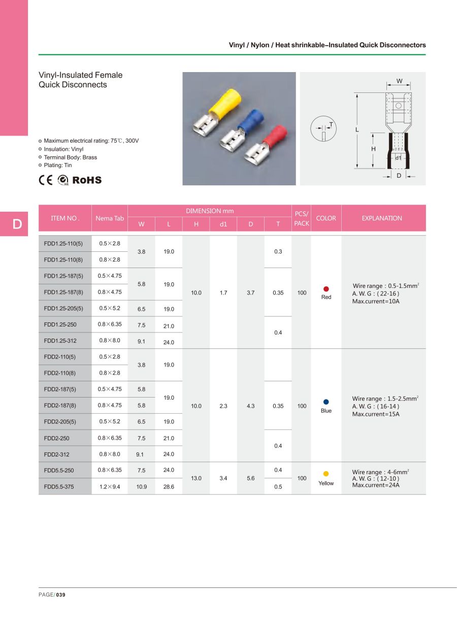
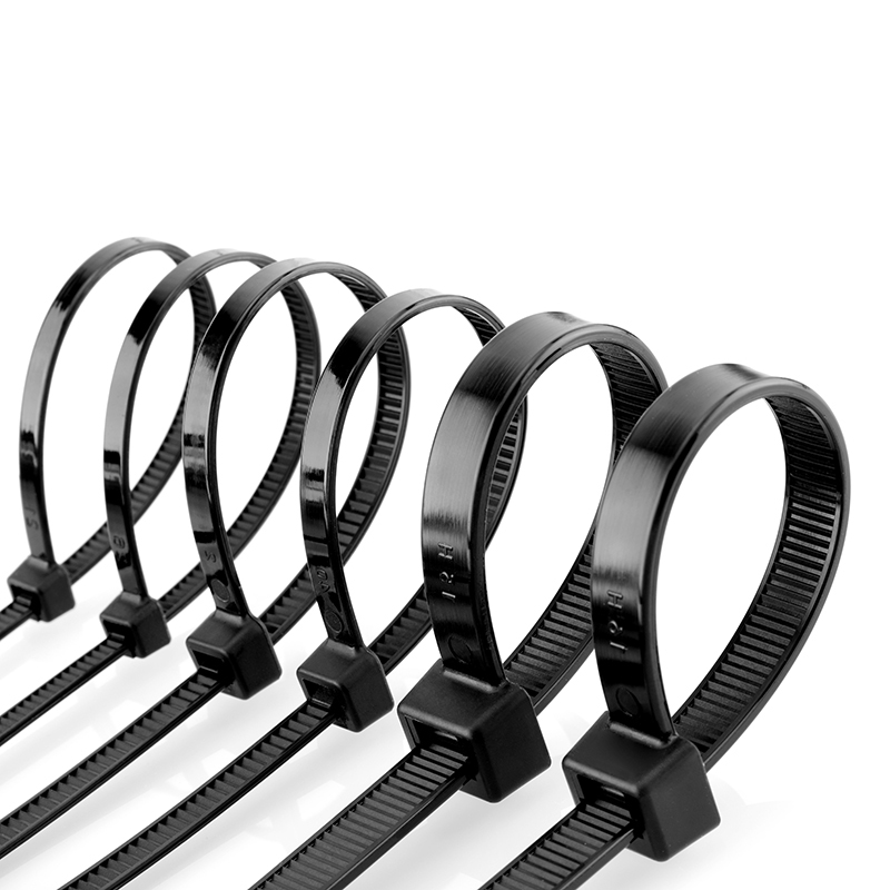
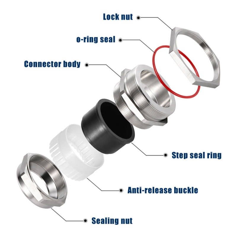
Images link to Niuli product pages (open in a new window). For the 90° flag female receptacle itself, specify the orientation on the 6.35 mm tab standard and crimp with a calibrated ratchet tool.
Frequently Asked Questions
What exactly is a flag female quick disconnect?
A flag female is a 90° (right-angle) female receptacle: it slides onto the male tab axially like any quick disconnect, but its wire barrel is bent 90° so the conductor exits to the side, parallel to the mounting face. RS PRO’s nylon-insulated version measures about 16 mm overall and is UL-recognized.
How does a flag female save vertical clearance versus a straight female?
A straight female keeps the wire collinear with the tab, so it projects forward and needs that length of free space in front of the terminal — space that sits in the vertical pitch. A flag female turns the wire 90°, so that length becomes a lateral run along the wall. The connection’s vertical footprint shrinks to roughly the tab width (~6–8 mm), inside a typical 8–12 mm terminal pitch.
What tab size do smart-meter flag females use?
The meter standard is 6.35 × 0.8 mm (0.250 in × 0.032 in); lighter signal circuits may use 4.75 × 0.8 mm (0.187 in). The male tab on the meter decides the receptacle. Niuli’s quick disconnects are built on the 6.35 mm tab standard.
Are flag females fully insulated?
They are available fully nylon-insulated (105 °C, tin-plated brass, UL-recognized, RoHS/REACH). In a dense meter box, fully insulated flag females prevent accidental shorts between adjacent landings — the safer choice over bare terminals.
Which wire sizes fit a 0.250 in flag female?
Typically 22–18 AWG (red), 16–14 AWG (blue) and 12–10 AWG (yellow) for the three insulation colour bands. Niuli’s matching ratchet crimp tool covers 0.25–6 mm² (24–10 AWG) across the disconnect family.
Do flag females need more force to crimp than straight ones?
No — the crimp is on the same barrel profile; only the exit is bent. Use a calibrated ratchet tool and finish the full stroke. A partial crimp raises resistance and can let the 90° exit relax forward, undoing the clearance gain.
Can I still service the connection in a tight box?
Yes — arguably easier. Because the wire exits sideways, you mate and unmate the receptacle from the side without pulling the conductor axially, which is exactly what a shallow enclosure leaves room for.
Will the 90° wire run short against the neighbour’s pitch?
That is the point of the flag: the vertical footprint is the tab width (~6–8 mm), well within a standard 8–12 mm pitch, so it does not intrude on the adjacent landing. Secure the lateral run with cable ties so vibration can’t push it back.
What standard covers these disconnects?
Quick-disconnect terminals are commonly built to UL 1977 (components) and are RoHS/REACH compliant; meter bodies follow standards such as GB/T 38317.22 for B-type smart meters (body thickness 71–85 mm). Niuli’s disconnects carry CE/RoHS/SGS.
Niuli sells quick disconnects — do you offer the flag orientation and crimp tool?
Niuli manufactures insulated male & female quick disconnects on the 6.35 mm tab standard plus a matching ratchet crimp tool (0.25–6 mm²). For a compact meter box, specify the 90° flag female on that tab standard and route the exited wire parallel to the meter face; Niuli’s brass glands seal the cable at the enclosure entry. Questions? Contact Niuli engineers.
Conclusion
In a compact smart-meter enclosure, vertical clearance — not box depth — limits how many circuits you can land on the terminal strip. A flag female quick disconnect keeps the axial mating mouth but bends the wire 90°, turning the straight female’s forward pull/withdrawal length into a lateral run along the wall. The connection’s vertical footprint collapses to the tab width (~6–8 mm), fitting inside the 8–12 mm terminal pitch so you can pack more rows or choose a smaller box. Match the 6.35 mm (0.250 in) tab standard, crimp fully with a calibrated ratchet tool, bundle the lateral run with nylon ties, and seal the cable entry with a brass gland — and the meter box stays serviceable instead of cramped.
Building a compact smart-meter enclosure? Get Niuli’s quick disconnects, crimp tool & routing hardware.
Related:
Hex vs Square Crimp & Battery Cable Resistance ·
DIN 46228 Ferrule & Strand Splitting ·
PG to Metric Adapter IP Failure