



Cable Glands · EMC
By Niuli Electric · Cable Gland Engineering Team · 9 min read
Key Takeaways
EMC brass cable glands ground a VFD motor cable’s shield around its full 360° circumference using a spring-finger contact, giving high-frequency PWM noise a low-impedance path to the enclosure instead of letting it radiate as EMI or travel through motor bearings.
Nickel-plated brass bodies add corrosion resistance and continuous conductivity, so the bond stays reliable under vibration and thermal cycling—exactly where a pigtail ground fails.
Why VFD Motors Generate EMI That Must Be Grounded
A Variable Frequency Drive switches DC bus voltage at high frequency to synthesize a variable AC output. Those PWM pulses have extremely fast voltage rise times (high dV/dt), which inject common-mode currents onto the motor cable. Without a continuous shield grounded at both ends, that cable behaves like a radio antenna.
The consequences are well documented in industrial drives:
- Radiated EMI leaks into nearby sensor, encoder, and communication lines, causing ghost faults and comm loss.
- Bearing currents seek a path through the motor shaft, producing electrical discharge machining (EDM) that pits and flutes the bearing races.
- Ground loops and RCD trips appear when noise finds an unintended route back to the supply earth.
This is why EMC brass cable glands and 360-degree shield grounding are not optional extras on a VFD—they are the difference between a quiet, reliable drive and a noisy one that eats bearings.
What “360-Degree Shield Grounding” Means
360-degree shield grounding means the cable’s braided or foil shield is bonded to the metal enclosure around its entire circumference—not via a single twisted pigtail wire. The shield becomes a continuous Faraday cage that traps high-frequency noise and returns it to the enclosure at the lowest possible impedance.
At the kilohertz-to-megahertz spectrum a VFD produces, a pigtail is no longer a “ground”—it is an inductor. Its reactance rises with frequency, so it blocks the very noise it is meant to drain. Only a full circumferential bond keeps the impedance low enough to actually work.
How an EMC Brass Cable Gland Achieves 360° Contact
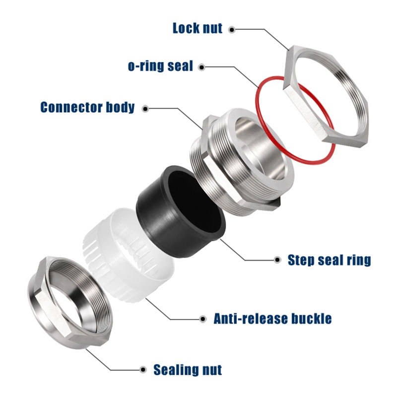
An EMC brass cable gland is built from a conductive nickel-plated brass body and nut, plus an internal spring-finger (crown) contact. The mechanism is straightforward:
- The installer strips the outer jacket to expose the braided shield.
- The braid is folded back over the gland’s sealing cone so it surrounds the fitting.
- Tightening the cap nut compresses the spring-finger evenly around the full 360° of the braid.
- The compressed spring creates permanent metal-to-metal bonding between shield, brass body, and the enclosure wall.
Because the contact is spring-loaded, it maintains pressure under vibration and thermal expansion—the exact conditions that loosen a soldered pigtail. The nickel plating protects the brass from oxidation, keeping contact resistance low for the life of the installation.
EMC Brass Gland vs Pigtail vs Standard Brass
| Method | 360° contact | High-freq performance | Vibration stability | IP rating |
|---|---|---|---|---|
| Pigtail ground | No | Poor (inductive) | Loosens | None |
| Standard brass gland (no spring) | Partial | Moderate | OK | IP68 |
| EMC brass gland (spring-finger) | Yes | Excellent | Stable | IP68 |
Step-by-Step: Correct EMC Gland Installation for VFD Cable
- Select size: match the metric/NPT thread to your panel and the clamping range to the shielded cable’s outer diameter.
- Strip jacket: remove the outer jacket to the specified length to expose the braid—do not nick the shield.
- Fold braid back: lay the braid evenly over the sealing cone so it encircles the fitting.
- Seat the gland: insert the cable and tighten the body to the enclosure to establish the enclosure bond.
- Compress the spring: tighten the cap nut until the spring-finger clamps the braid at a full 360°.
- Torque & verify: tighten to the manufacturer spec and confirm shield-to-enclosure continuity with a bonding tester.
- Repeat at the motor end: ground the shield at both the drive and motor terminal box for a closed Faraday path.
Common Mistakes That Break Shield Grounding
- Using a pigtail instead of 360° bonding—the single most common EMI root cause.
- Plastic (nylon) glands for EMC—non-conductive bodies cannot shield at all.
- Over-tightening and crushing the braid, which breaks the continuous contact.
- Mixed ground paths that create ground loops and confuse RCDs.
- Loose termination that forms a high-resistance hot spot in humid plants.
Niuli EMC-Capable Brass & Stainless Glands
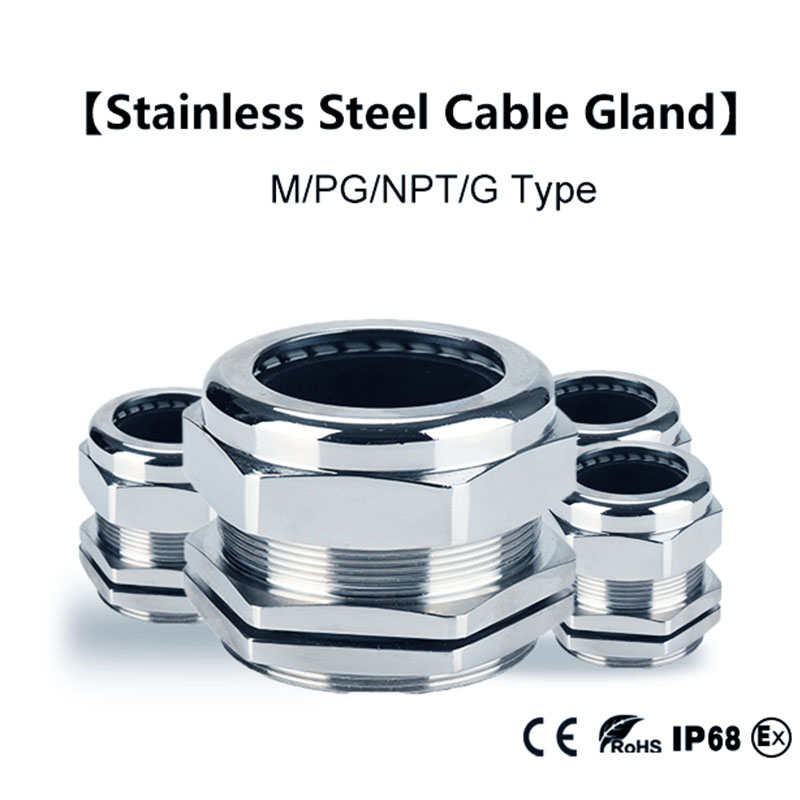
For VFD and automation builds, Niuli supplies nickel-plated brass cable glands that provide the conductive, corrosion-resistant body a 360° EMC termination needs—IP68 sealed, rated −40 °C to +100 °C, with CE / RoHS / SGS certification. For corrosive or coastal sites, our 304 / 316 stainless steel cable glands extend service life further.
When specifying, request the spring-finger EMC variant so the gland delivers true 360° shield grounding rather than basic sealing only. See our full cable glands range or read 7 things you should know about brass cable glands for material and selection detail.
Need EMC brass glands spec’d for your VFD drive?
Frequently Asked Questions
What is 360-degree shield grounding in a VFD system?
It bonds the motor cable’s braided shield to the metal enclosure around its full circumference—not with a single pigtail wire. This gives high-frequency VFD noise a continuous low-impedance path to ground, preventing it from radiating as EMI or traveling through motor bearings. Explore Niuli’s brass cable glands →
Why is pigtail grounding ineffective for VFD cables?
A pigtail is a short wire twisted from the shield to ground. At the kHz–MHz frequencies a VFD generates, that wire acts like an inductor, creating reactance that blocks noise instead of draining it—leaving a residual antenna that still radiates EMI. Ask our engineers why →
How does an EMC brass cable gland achieve 360° contact?
A spring-finger (crown) contact inside the gland clamps the laid-back shield braid around its entire circumference. Tightening the cap nut compresses the spring evenly, creating permanent metal-to-metal bonding between shield and the conductive nickel-plated brass body—and thus the enclosure. See the brass gland specs →
Are nickel-plated brass EMC glands corrosion resistant?
Yes. The nickel plating protects the brass substrate from oxidation while preserving high conductivity, keeping contact resistance low for years. For coastal or chemical plants, our stainless steel cable glands add further protection. Request a corrosion guide →
Can EMC brass glands be used on both the VFD and motor ends?
Absolutely. Best practice grounds the shield at both the drive enclosure and the motor terminal box using EMC glands at each end. This closes the Faraday cage along the whole cable run and gives common-mode noise a consistent return path. Browse the gland range →
What thread types and sizes are available?
Industrial EMC brass glands ship in metric (M), PG, NPT, and G threads across a wide cable-range table (e.g., M12–M100). Choose the thread matching your panel and a clamping range that fits the shielded cable’s outer diameter plus termination allowance. View all thread options →
Do EMC glands help prevent VFD bearing currents?
They help significantly. By draining high-frequency common-mode current through the enclosure instead of through the motor shaft, 360° grounding reduces the shaft voltages that cause bearing fluting (EDM damage). Pair with shaft-grounding rings for severe cases. Discuss your drive setup →
What IP and temperature ratings should I specify?
Specify at least IP65 for indoor panels and IP68 for outdoor or washdown VFD installations. Niuli nickel-plated brass EMC glands typically cover −40 °C to +100 °C, suiting most motor drives and factory environments. Check brass gland ratings →
How do I install an EMC brass cable gland correctly?
Strip the jacket to expose the braid, fold the braid back over the sealing cone, insert the cable, and tighten the cap nut so the spring-finger compresses the braid 360°. Torque to spec and verify shield-to-enclosure continuity with a bonding tester. Get install specs →
Which certifications matter for EMC cable glands?
Look for CE and RoHS as baselines, plus compliance with cable-gland standard IEC 62444 and EMC directives (e.g., IEC 61326 / EN 50262 for screened glands). Independent SGS or UL listings add confidence for export and regulated industries. See Niuli certifications →
Conclusion
A VFD is only as quiet as its cable termination. EMC brass cable glands turn shield grounding from a pigtail afterthought into a true 360° bond, draining PWM noise at the source and protecting both your signal integrity and your motor bearings. Specify the spring-finger EMC variant in nickel-plated brass—or stainless for harsh sites—and verify continuity at install.
Related Resources
Specify 360° EMC grounding on your next VFD build
Niuli Electric is a cable gland manufacturer. Product specifications should be confirmed against the latest datasheet and local EMC wiring codes before installation.
