


Introduction
Cable management inside an offshore wind turbine tower is a different job from bundling a few wires in a control cabinet. Power cables can be heavy, vertical runs can run the length of the tower, and the whole system lives with vibration and movement for twenty-plus years.
So the practical question becomes: how far apart can stainless steel cable ties be installed before the load on each one gets excessive?
For 316 stainless steel ball-lock ties, you can’t read the answer straight off the tensile-strength figure. The actual spacing depends on the weight of the cable bundle, the direction of the run, vibration and dynamic loading, the required safety factor, cable sag, and how the cable attaches to the tower.
Niuli’s stainless steel ball-lock ties come in several widths and lengths. Its current range includes 4.6 mm ties rated at 250 lbs minimum loop tensile strength, 7.9 mm at 340 lbs, 10 mm at 480 lbs, and 12 mm at 675 lbs. The products are available in 316 stainless steel as well as 201 and 304 grades. (Niuli Electric)
Here’s the point worth repeating: minimum loop tensile strength is a product rating. It is not a recommended cable-support load, and it is not a maximum span. The spacing still has to be engineered for the actual installation.
Why Does Span Distance Matter on Offshore Wind Turbine Towers?
A long vertical cable run has a simple problem: gravity.
If a cable is secured only at widely spaced points, each tie carries the weight of the cable between its support points. Longer unsupported section, higher load on each fastening point.
On a wind turbine tower, gravity isn’t the only issue. The cable system may also see:
- Tower vibration
- Cable movement
- Start-up and shutdown cycles
- Temperature changes
- Wind-induced movement of the tower and cable support system
- Dynamic loads during turbine operation
IEC 61400-1 covers the overall design requirements for wind turbines and explicitly includes internal electrical systems among the turbine subsystems considered in the design. DNV-ST-0437 provides requirements and guidance for determining wind-turbine loads and site conditions, including offshore applications.
That doesn’t turn a cable tie into a structural component of the tower. In most installations it’s one part of a larger cable-support arrangement.
The spacing question therefore has two sides:
- Mechanical capacity: can the tie carry the load?
- Cable-support requirements: is the spacing close enough to control movement, sag, vibration, and long-term fatigue?
The second question can govern even when the tie’s tensile capacity looks more than sufficient.
What Factors Determine the Maximum Span Distance?
Cable Weight and Bundle Diameter
Cable weight is the starting point.
Suppose a vertical cable bundle weighs 8 kg per meter. With supports 2 m apart, the weight attributable to that section is approximately:
8 kg/m × 2 m = 16 kg
A support point doesn’t necessarily carry exactly half of this in every real installation. Load distribution depends on the geometry, how the cable is attached, and whether the cable is continuous or independently supported.
For a quick preliminary check, though, cable weight per unit length × support spacing gives a useful first estimate of the load the fastening system may see.
Bundle diameter matters too. A larger bundle may need a wider, stronger tie, and a larger tie may carry a different minimum loop tensile-strength rating.
Niuli’s product range makes this relationship visible: its 4.6 mm tie is rated at 250 lbs, the 7.9 mm tie at 340 lbs, the 10 mm tie at 480 lbs, and the 12 mm tie at 675 lbs minimum loop tensile strength. (Niuli Electric)
316 Stainless Steel Tie Tensile Strength
316 stainless steel is attractive offshore because it resists corrosion well in chloride-bearing conditions.
But when you calculate span, the number that matters isn’t the stainless steel grade. It’s the minimum loop tensile strength of the exact cable-tie model.
Niuli’s 316-capable self-locking range includes:
| Tie Width | Minimum Loop Tensile Strength |
| 4.6 mm | 250 lbs / 110 kg |
| 7.9 mm | 340 lbs / 150 kg |
| 10 mm | 480 lbs / 210 kg |
| 12 mm | 675 lbs / 300 kg |
These are product ratings from Niuli’s catalogue. Don’t treat them as allowable working loads without an engineering assessment and an appropriate safety margin. (Niuli Electric)
For a critical offshore application, it’s also worth remembering that the tie doesn’t operate in a laboratory. Corrosion, fatigue, installation damage, edge contact, and repeated dynamic loading can all eat into the margin available in service.
Wind, Vibration, and Dynamic Loading
Offshore wind turbines are highly dynamic structures.
The tower moves, machinery vibrates, and the cable system may see repeated movement throughout the turbine’s operating life. DNV-ST-0437 is specifically concerned with determining design loads and site conditions for wind turbines, while IEC 61400-1 addresses the broader structural integrity of the turbine and its subsystems.
For cable support, this means a static weight calculation is only a starting point.
A practical calculation can introduce a dynamic factor to account for additional loading. The appropriate factor should come from the project’s engineering methodology — it should not be invented simply to make a calculation work.
For an article or preliminary sizing exercise, it’s reasonable to show the effect of a safety or dynamic factor using an assumed value, but that value must be clearly identified as an example rather than an offshore wind design requirement.
Cable Sag and Installation Safety
Even if a tie can withstand the calculated weight, that doesn’t mean the cable should be left on a very long span.
Long unsupported cable sections can sag, move, or strike nearby structures. Offshore wind towers also contain confined spaces, ladders, platforms, electrical equipment, and other components that cable runs need to clear.
So support spacing has a practical limit that may sit well below the tie’s tensile limit.
Cable ties also should not be treated as substitutes for engineered cable cleats or structural cable-support systems where the project design requires those.
A useful way to think about it:
Tie strength determines whether the fastening can carry the load. Support spacing determines how the cable behaves between fastening points.
Both need to be checked.
How to Calculate the Maximum Span Distance
Basic Span and Load Calculation
For a preliminary vertical cable-support calculation, a simple relationship works:
F = w × s
Where:
- F = load carried by one support
- w = cable weight per unit length
- s = support spacing
If a cable bundle weighs 8 kg/m and ties are installed every 2 m:
F = 8 × 2 = 16 kg
You can then compare the calculated support load with the selected tie’s available capacity.
When working from minimum loop tensile strength, a safety factor is needed:
Required tensile capacity ≥ w × s × SF
Rearranging gives a preliminary maximum spacing:
smax = Ftie / (w × SF)
where Ftie is the relevant tie strength and SF is the selected safety factor.
This is a useful screening equation, but it has an important limitation: it assumes the tie carries the calculated load in a simple static arrangement. It does not account for every aspect of an offshore wind cable-support system.
Applying a Safety Factor
Never design the span right up to the published minimum loop tensile strength.
For example, suppose a project uses the Niuli 12 mm stainless steel tie rated at 675 lbs (300 kg). With an illustrative safety factor of 3 and an assumed cable bundle weight of 10 kg/m:
smax = 300 ÷ (10 × 3) = 10 m
That 10 m figure is a mathematical result from the assumed inputs. It is not a recommendation to install ties every 10 m on a wind turbine.
Why not?
Because the tie’s tensile rating is only one part of the system. Cable movement, sag, vibration, support geometry, fatigue, local contact stress, and the turbine manufacturer’s own requirements can all push the practical spacing much smaller.
For an offshore wind project, the safety factor and dynamic loading criteria should come from the project’s design basis.
Worked Example for Offshore Wind Cable Bundles
Consider a simplified vertical cable run:
- Cable bundle weight: 10 kg/m
- Selected tie: 12 mm 316 stainless steel
- Minimum loop tensile strength: 300 kg / 675 lbs
- Illustrative safety factor: 3
Using:
smax = Ftie / (w × SF)
we get:
smax = 300 / (10 × 3) = 10 m
Now reduce the spacing to 2 m:
Load per support = 10 × 2 = 20 kg
The calculated load sits well below the tie’s nominal tensile rating.
This illustrates something useful: the maximum spacing based on tensile capacity may be much larger than the spacing that makes sense for cable support.
A project engineer may choose a substantially closer spacing to control cable movement and sag. A 1–2 m preliminary spacing might be worth investigating, for example, but the actual value must come from the cable manufacturer’s requirements, the turbine design, and the support arrangement.
So use this calculation as a capacity check, not as the final installation specification.
Why Choose 316 Stainless Steel Ball-Lock Ties for Offshore Wind Towers?
Superior Corrosion Resistance in Saltwater Environments
Offshore wind equipment operates in a salt-laden environment with high humidity and repeated wetting. Stainless steel is a common choice for exposed fastening hardware for that reason.
316 stainless steel is particularly useful where chloride exposure is a concern. Niuli offers 201, 304, and 316 stainless steel cable ties, so the material grade can be matched to the installation environment. (Niuli Electric)
That doesn’t mean 316 eliminates corrosion under all offshore conditions. Surface contamination, crevices, galvanic contact, and installation damage still matter. It does provide a stronger corrosion-resistance baseline than lower-alloy stainless grades in chloride-rich environments, though.
High Tensile Strength and Secure Ball-Lock Mechanism
Niuli’s stainless steel ties use a ball-lock mechanism and are designed for high-strength fastening. Its 4.6 mm model is rated at 250 lbs, while larger versions increase to 340 lbs, 480 lbs, and 675 lbs. (Niuli Electric)
The ball-lock design also keeps the head relatively compact. Niuli describes its stainless steel ties as low-profile with smooth rounded edges. (Niuli Electric)
In a turbine tower, where space is tight and the fastening has to hold, that’s a practical combination.
Resistance to Extreme Temperature and UV Exposure
Offshore equipment can see substantial temperature variation over its service life, even though the tower interior is generally less exposed than external structures.
Niuli specifies a working-temperature range of -60°C to 550°C for its self-locking stainless steel tie range. (Niuli Electric)
That specification gives a wide material operating range for high- and low-temperature industrial applications.
For actual offshore wind deployment, though, the complete fastening arrangement still needs to be evaluated against the project’s environmental and mechanical conditions.
How to Select the Right 316 Stainless Steel Tie Size?
Start with the cable bundle rather than the tie.
Measure the bundle diameter and determine the total weight that each support will need to carry.
Then check the tie’s:
- Width
- Length
- Thickness
- Maximum bundle diameter
- Minimum loop tensile strength
- Locking design
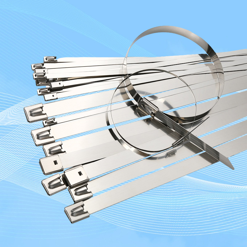
Niuli’s 4.6 mm, 7.9 mm, 10 mm, and 12 mm stainless steel ties cover a wide range of bundle sizes and load requirements. The product page lists maximum bundle diameters from around 25 mm for smaller models to 78 mm and more for larger formats. (Niuli Electric)
For offshore wind towers, also think about the support point itself. If the tie wraps around a cable bundle but has no proper structural attachment to the tower, a stronger tie doesn’t solve the underlying support problem.
Where cable protection is needed against hard or sharp surfaces, the use of a suitable protective interface should also be considered.
Why Choose Niuli Electric 316 Stainless Steel Ball-Lock Ties?
Niuli Electric’s stainless steel tie range includes SUS201, SUS304, and SUS316, with ball-lock construction and customizable width and length. The self-locking range is listed for temperatures from -60°C to 550°C and carries CE and RoHS certifications. (Niuli Electric)
The 316 option is particularly relevant to offshore and marine environments because of the alloy’s corrosion resistance. Niuli also provides coated stainless steel tie options where an additional protective layer is needed. Its epoxy-coated series uses 201/304/316 stainless steel substrates and is designed to add edge protection, corrosion resistance, and UV resistance. (Niuli Electric)
For large B2B orders, Niuli supports customized width and length, as well as OEM/ODM packaging. The company also states that it maintains incoming-material, production, finished-product, and pre-shipment inspection procedures. (Niuli Electric)
For offshore wind procurement, this means the tie can be specified around the actual cable bundle and installation geometry instead of forcing the project into a fixed catalogue size.
FAQs
Q1. Can I calculate the maximum cable-tie spacing from tensile strength alone?
No. Tensile strength gives a useful capacity check, but it doesn’t establish the final support spacing. Sag, cable movement, vibration, dynamic loads, fatigue, and the structural attachment point all matter too.
Q2. What is the basic formula for maximum span?
For a simplified static vertical-support calculation:
smax = Ftie / (w × SF)
where Ftie is the available tie capacity, w is cable weight per unit length, and SF is the selected safety factor.
It’s a preliminary screening formula, not a complete offshore-wind cable-support design method.
Q3. What is the tensile strength of Niuli 316 stainless steel ball-lock ties?
Niuli’s current self-locking range includes 4.6 mm ties rated at 250 lbs / 110 kg, 7.9 mm at 340 lbs / 150 kg, 10 mm at 480 lbs / 210 kg, and 12 mm at 675 lbs / 300 kg minimum loop tensile strength. (Niuli Electric)
Q4. Does a 675 lb cable tie mean I can support 675 lb of cable?
No. The published value is a minimum loop tensile strength, not a recommended working load. A suitable design safety factor and the actual loading conditions must be considered.
Q5. Why use 316 instead of 304 offshore?
316 generally resists chloride-rich environments better than 304, which helps in marine and offshore conditions. The final material choice should still consider the actual exposure and project specifications.
Q6. Are cable ties suitable as the primary support for heavy power cables?
Not necessarily. For heavy power cables, the primary support system may require engineered cable cleats, clamps, trays, or other structural supports. Cable ties can serve as part of the cable-management system where their use is appropriate.
Q7. How often should cable ties be installed on a wind-turbine tower?
There is no universal spacing value. It depends on cable weight, cable construction, support arrangement, vibration, sag requirements, and the turbine or cable manufacturer’s specifications.
Q8. Can Niuli customize stainless steel cable-tie dimensions?
Yes. Niuli states that width and length can be customized for its stainless steel tie range. (Niuli Electric)
Conclusion
Calculating a maximum span for 316 stainless steel ball-lock ties starts with a simple relationship between cable weight and support spacing, but the calculation shouldn’t stop there.
A tie installed every few meters may carry only a fraction of its published tensile strength, yet the same spacing can still be unsuitable if the cable is allowed to move, sag, or vibrate excessively. Offshore wind turbines are dynamic structures, and cable-support design has to account for those conditions. IEC 61400-1 and DNV-ST-0437 provide the broader framework for wind-turbine design and load assessment.
For preliminary sizing, the equation
smax = Ftie / (w × SF)
is useful for checking whether tensile capacity is even in the right range. The final support spacing should come from the complete cable-support design.
Niuli’s 316 stainless steel ball-lock cable ties, available in widths from 4.6 mm to 15 mm and with minimum loop tensile strengths up to 675 lbs / 300 kg, provide several options for high-strength industrial cable management. (Niuli Electric)
For an offshore wind application, the best specification combines the right 316 stainless steel grade, tie size, tensile capacity, support spacing, and mounting method rather than relying on one tensile-strength number.
Explore the Niuli Stainless Steel Tie Catalog or Request Free Samples to evaluate a suitable specification before bulk purchasing.
For project-specific span calculations, provide the cable weight per meter, bundle diameter, support arrangement, and required safety factor when contacting Niuli Electric so the appropriate tie size can be evaluated.
